Table of Contents
Introduction
Structural steel drawings are the backbone of any fabrication and construction project. They provide a detailed roadmap for welders, fabricators, and site crews to bring an engineer’s design into reality. Yet, many builders and contractors find Tekla structural steel drawings overwhelming because of the technical symbols, abbreviations, and codes involved.
In this guide, we’ll break down the essentials of reading Tekla-generated steel drawings in a way that’s easy to understand and apply on-site. Whether you’re a builder in Adelaide or a project manager handling a commercial development in South Australia, this article will help you decode structural steel drawings with confidence.
What Are Tekla Structural Steel Drawings?
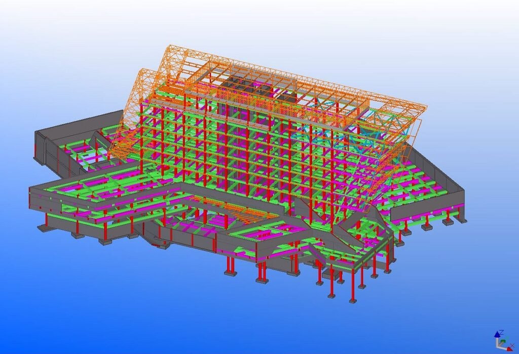
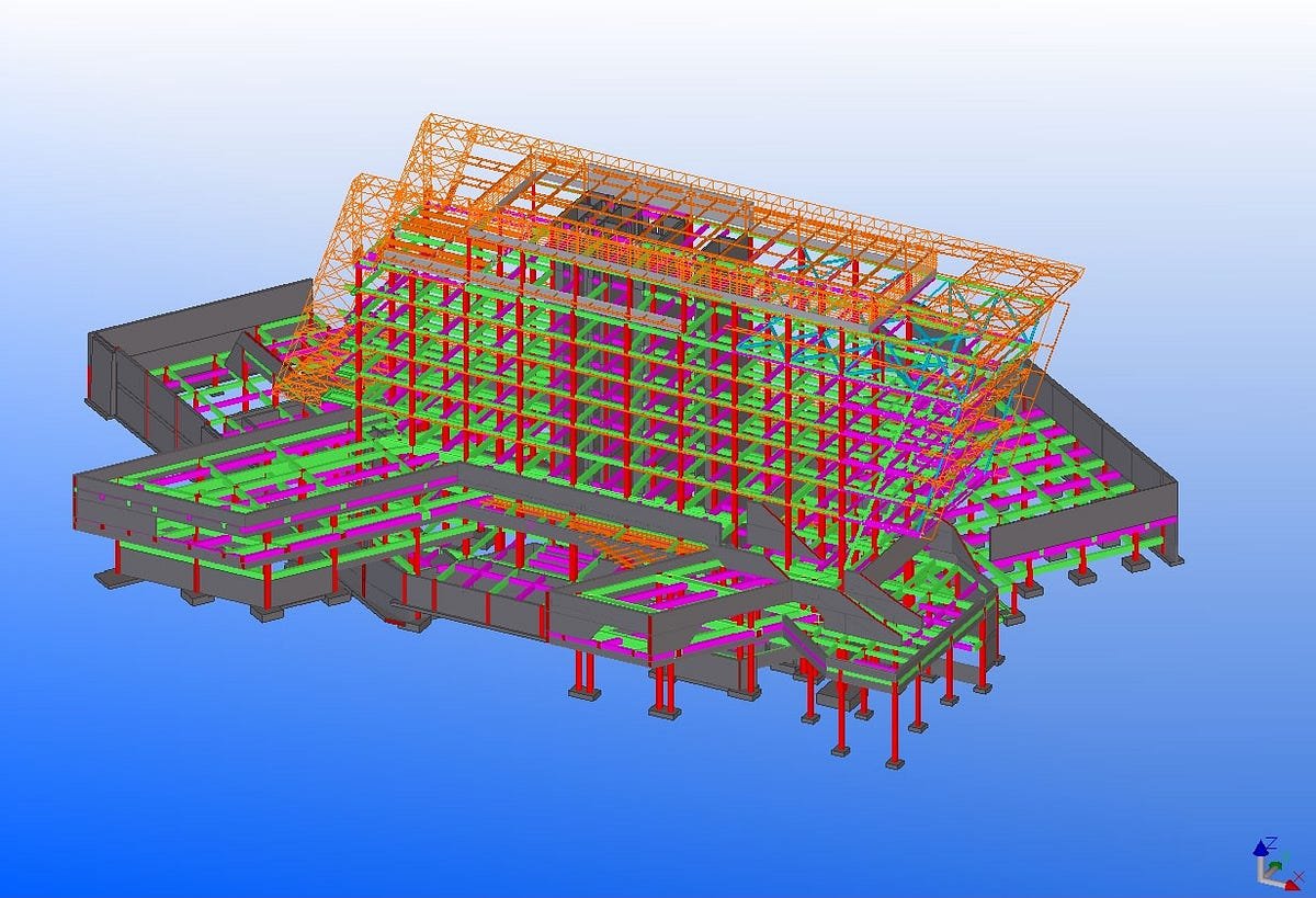
Tekla Structures is an advanced 3D Building Information Modelling (BIM) software widely used in the construction industry for steel detailing. With Tekla, draftsmen create fabrication-ready 3D models that can be converted into highly accurate shop drawings and erection plans.
Unlike traditional 2D drafting, Tekla drawings ensure:
- Accurate part dimensions
- Clear welding and bolting specifications
- Clash detection before construction begins
- Smooth communication between engineers, fabricators, and site crews
Reference: Tekla Structures official site – Trimble.
Why Tekla Drawings Are Important for Steel Construction
- Precision and Accuracy – Tekla’s 3D modelling reduces human errors common in manual drafting.
- Clarity for Fabrication – Welders and fabricators get precise instructions for cutting, welding, and assembling.
- Seamless Coordination – Ensures architects, engineers, and builders are on the same page.
- Time and Cost Savings – Minimizes rework, prevents clashes, and improves project timelines.
This makes Tekla a standard in structural steel projects across Australia and globally.
Key Elements of Tekla Structural Steel Drawings
To read Tekla structural steel drawings effectively, you need to understand the main components included:
1. General Arrangement (GA) Drawings
- Provide an overall view of the structure
- Show how beams, columns, and braces fit together
- Used by site erection teams
2. Shop Drawings (Fabrication Drawings)
- Contain exact dimensions of individual steel members
- Show weld symbols, cut lengths, and hole placements
- Used by fabricators in workshops
3. Erection Drawings
- Highlight sequence and method of steel installation
- Include crane lifting points, splice locations, and site connections
4. Bolt and Weld Symbols
- Specify how components will be joined
- Example: “M20 bolt @ 200mm c/c” means M20 bolts at 200mm spacing
Common Symbols in Tekla Steel Drawings
Understanding symbols is critical for accuracy on-site. Here are some of the most common:
- Weld Symbols – Triangle symbol = fillet weld, circle = spot weld
- Bolt Symbols – Crossed circle indicates a bolted hole
- Section Lines – Show cut-through views of a structure
- Reference Marks – Identify member position (e.g., C1 for Column 1)
Reference: American Welding Society (AWS) – Weld Symbols Guide.
Step-by-Step: How to Read Tekla Structural Steel Drawings
Step 1: Start with the Title Block
- Check project name, drawing number, and revision status
- Ensure you’re working with the latest version
Step 2: Understand Scale and Dimensions
- Most Tekla drawings are to scale; confirm units (mm in Australia)
Step 3: Identify Structural Elements
- Look for beam, column, and bracing identifiers (B1, C1, BR1)
Step 4: Review Welds and Bolts
- Understand the joining method (MIG welds, SMAW, bolted connections)
Step 5: Cross-check with GA Drawings
- Verify how the part fits within the overall structure
Common Mistakes Builders Make with Tekla Drawings
- Ignoring Revision Numbers – Working with outdated drawings leads to costly rework.
- Misinterpreting Weld Symbols – Small mistakes can compromise safety.
- Overlooking Bolt Grades – Using incorrect bolts affects structural performance.
- Skipping Coordination – Failing to cross-check GA drawings causes installation delays.
Best Practices for Using Tekla Structural Steel Drawings On-Site
- Always verify drawing revision before starting work
- Use digital devices or printed drawings for clarity
- Conduct toolbox meetings with crews to explain drawings
- Coordinate with fabricators and engineers before modifications
- Store drawings in a central, easily accessible location
Advantages of Tekla Drawings for Builders and Contractors
- Reduced Rework – Clearer instructions mean fewer site changes
- Improved Collaboration – Engineers, architects, and builders align easily
- Faster Construction – On-site erection is smoother with pre-checked designs
- Quality Assurance – Ensures compliance with AS/NZS structural steel standards
Reference: Australian Steel Institute.
Tekla Drawings vs Traditional 2D Drafting
| Feature | Tekla Drawings | Traditional Drafting |
| Accuracy | High (3D clash detection) | Prone to manual errors |
| Collaboration | Limited to static 2D files | Real-time 3D coordination |
| Efficiency | Faster fabrication | Slower, manual checks needed |
| Cost Savings | Reduces rework | Higher chance of delays |
When to Seek Professional Help
If you’re struggling to interpret Tekla drawings, partner with a certified steel fabricator and detailer. At WeldMech Fabrication, our in-house Tekla team provides shop drawings, GA drawings, and site erection details that make construction smoother and faster. We also coordinate directly with your architects and engineers to minimize errors.
Conclusion
Reading Tekla structural steel drawings may feel technical at first, but with practice, you’ll quickly learn to interpret the symbols, dimensions, and weld notations that guide fabrication and erection. For builders and contractors in Adelaide and South Australia, mastering Tekla drawings means fewer mistakes, faster builds, and safer structures.
At WeldMech Fabrication, we specialise in Tekla drafting and detailing, structural steel fabrication, and on-site installation. With our expertise, you don’t just get drawings — you get clarity, precision, and confidence.
📞 Call us at +61 449 805 365 or ✉️ admin@weldmech.com.au to learn how we can support your next project.