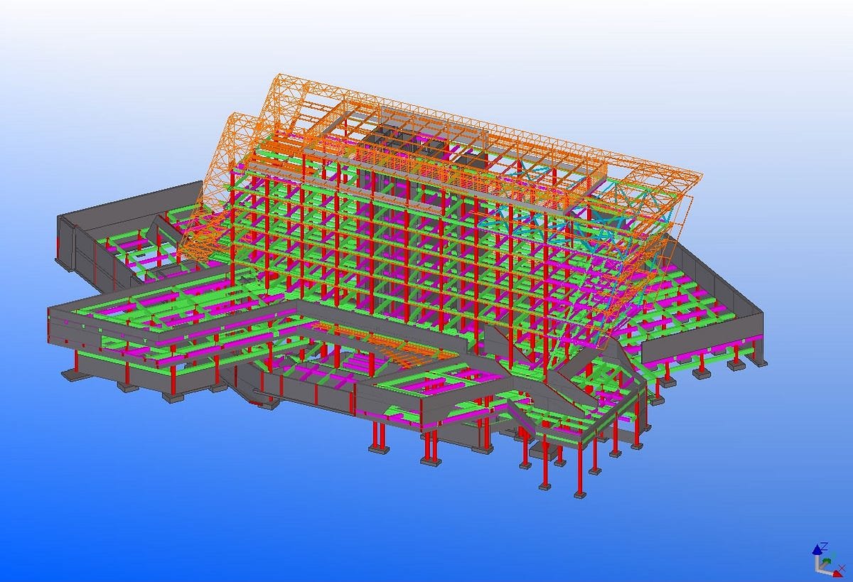
Introduction Structural steel drawings are the backbone of any fabrication and construction project. They provide a detailed roadmap for welders, fabricators, and site crews to bring an engineer’s design into reality. Yet, many builders and contractors find Tekla structural steel drawings overwhelming because of the technical symbols, abbreviations, and codes involved. In this guide, we’ll break down the essentials of reading Tekla-generated steel drawings in a way that’s easy to understand and apply on-site. Whether you’re a builder in Adelaide or a project manager handling a commercial development in South Australia, this article will help you decode structural steel drawings with confidence. What Are Tekla Structural Steel Drawings? Tekla Structures is an advanced 3D Building Information Modelling (BIM) software widely used in the construction industry for steel detailing. With Tekla, draftsmen create fabrication-ready 3D models that can be converted into highly accurate shop drawings and erection plans. Unlike traditional 2D drafting, Tekla drawings ensure: Reference: Tekla Structures official site – Trimble. Why Tekla Drawings Are Important for Steel Construction This makes Tekla a standard in structural steel projects across Australia and globally. Key Elements of Tekla Structural Steel Drawings To read Tekla structural steel drawings effectively, you need to understand the main components included: 1. General Arrangement (GA) Drawings 2. Shop Drawings (Fabrication Drawings) 3. Erection Drawings 4. Bolt and Weld Symbols Common Symbols in Tekla Steel Drawings Understanding symbols is critical for accuracy on-site. Here are some of the most common: Reference: American Welding Society (AWS) – Weld Symbols Guide. Step-by-Step: How to Read Tekla Structural Steel Drawings Step 1: Start with the Title Block Step 2: Understand Scale and Dimensions Step 3: Identify Structural Elements Step 4: Review Welds and Bolts Step 5: Cross-check with GA Drawings Common Mistakes Builders Make with Tekla Drawings Best Practices for Using Tekla Structural Steel Drawings On-Site Advantages of Tekla Drawings for Builders and Contractors Reference: Australian Steel Institute. Tekla Drawings vs Traditional 2D Drafting Feature Tekla Drawings Traditional Drafting Accuracy High (3D clash detection) Prone to manual errors Collaboration Limited to static 2D files Real-time 3D coordination Efficiency Faster fabrication Slower, manual checks needed Cost Savings Reduces rework Higher chance of delays When to Seek Professional Help If you’re struggling to interpret Tekla drawings, partner with a certified steel fabricator and detailer. At WeldMech Fabrication, our in-house Tekla team provides shop drawings, GA drawings, and site erection details that make construction smoother and faster. We also coordinate directly with your architects and engineers to minimize errors. Conclusion Reading Tekla structural steel drawings may feel technical at first, but with practice, you’ll quickly learn to interpret the symbols, dimensions, and weld notations that guide fabrication and erection. For builders and contractors in Adelaide and South Australia, mastering Tekla drawings means fewer mistakes, faster builds, and safer structures. At WeldMech Fabrication, we specialise in Tekla drafting and detailing, structural steel fabrication, and on-site installation. With our expertise, you don’t just get drawings — you get clarity, precision, and confidence. 📞 Call us at +61 449 805 365 or ✉️ admin@weldmech.com.au to learn how we can support your next project.